. 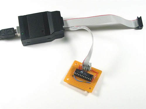
The target board basically provides a programming header that's hooked up to the right pins of the chip, plus some way to power the chip-- often through the programmer itself.
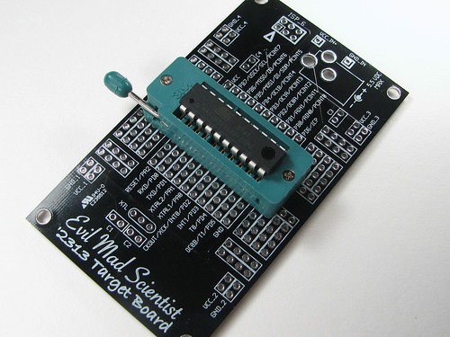
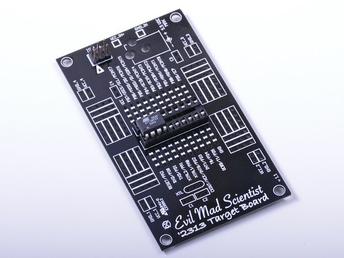
After hand-wiring up one too many minimalist '2313 boards like that, we also made a printed circuit board version of the '2313 target board. Normally, it looks something like this, with an ATtiny2313 in a ZIF socket:
But, back to the question. The ATtiny25, ATtiny45, and ATtiny85 are a family of 8-pin AVR microcontrollers that are not pin compatible with the '2313. However, at only 8 pins instead of 20 pins, they'll definitely fit in the socket... somewhere.
Looking at the datasheets and pinouts for the the '45, '2313 (and the '168 that we also have a target board for), we can identify the lines used for programming: MISO, MOSI, SCK, and RESET:
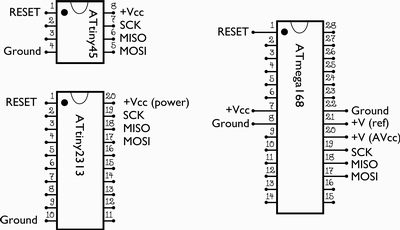
The chips also need power and ground connections to be programmed, of course. Now if you notice, the connections for the '2313 and '45 are very similar-- in fact, almost identical if you line the chip up so that pin 1 goes where pin 1 of the '2313 normally would. The one remaining difference is that there's no ground connection to pin 4 of the '2313.
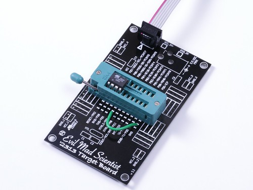
So, adding a wire from ground-- pin 10 of the '2313 --to pin 4 of the smaller chip (an ATtiny25 in our photo), and lining up pin 1 to pin 1, we're ready to go. And yes, it works like a charm.
If you do use this method, there are a few (possibly obvious) things worth noting:
- You need to be careful to line up pin 1 of the chip to pin 1 of the socket.
- Be careful if or when you put a '2313 chip back in the socket. It will draw a lot of current if you set pin 4's to a high output level-- it's shorted to ground. (Better: If you want to go back and forth, use a switch, not a wire.)
- Keep in mind that the pin labels on the target board are for the '2313, not the '85.
Going one step further, you could also potentially program the '25/'45/'85 from the '168 target board: it only takes a couple more wires. To do so, line up pin 1 of the '25 to pin 9 of the '168. Add two wires this time, from board-reset to chip-reset, and from board-ground to chip-ground. You'll also need to connect AVCC (analog power supply) to VCC. A little more work, yes, but still a good hack.

No comments:
Post a Comment